
America's most complete information resource for the pipe organ technician or hobbyist.
|
America's most complete information resource for the pipe organ technician or hobbyist. |
THIS ARTICLE DEFINES A METHOD FOR PROPERLY INSTALLING ELECTRO-MECHANICAL STOP SWITCHES ON AN EXISTING THEATRE ORGAN CONSOLE. |
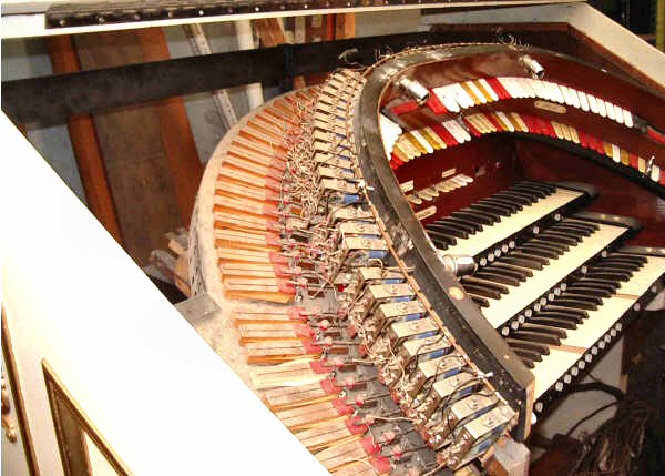
The first two photos in the series illustrate an unsatisfactory attempt that had been performed earlier. The remainder of the photos indicate how author, Julien Arnold, went about correcting this situation to provide a beautifully executed console expansion The author can be contacted at: julienarnold (at) hotmail.com ..(be sure to replace the (at) with @) |
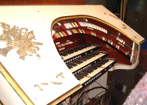 |
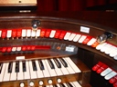
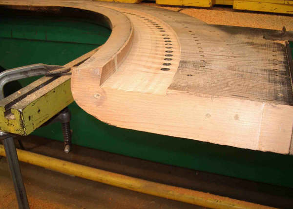
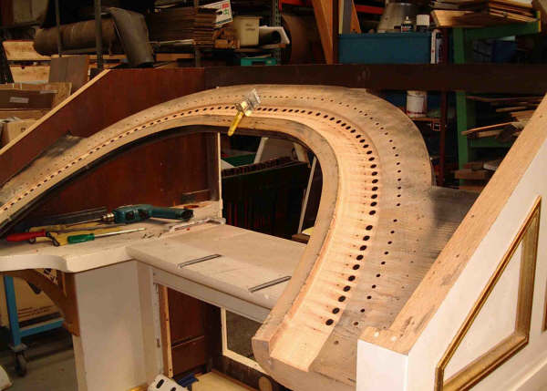
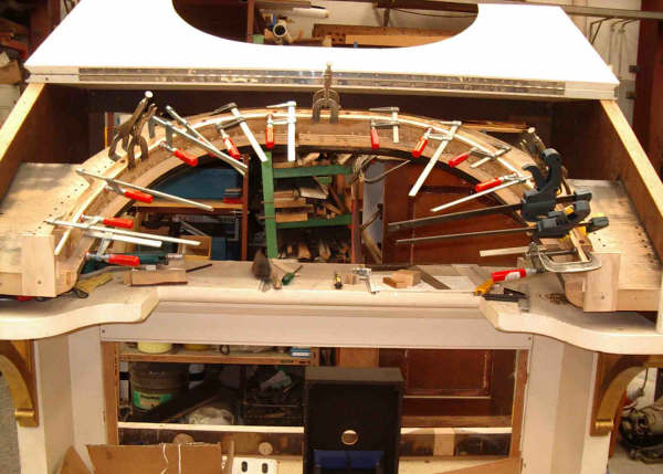
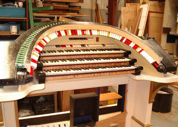
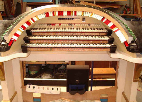
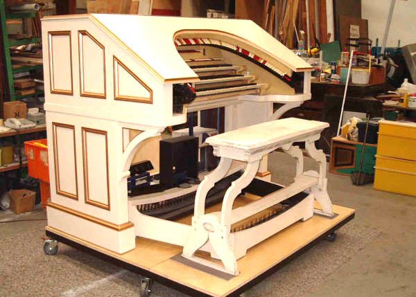
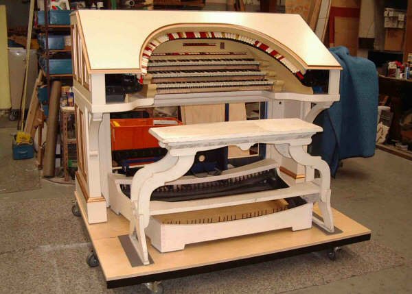
3 man console as received with second row of Reisner SAMs and added top stop rail. |
 |
PHOTOS ABOVE:Showing added Reisners and added top rail. |
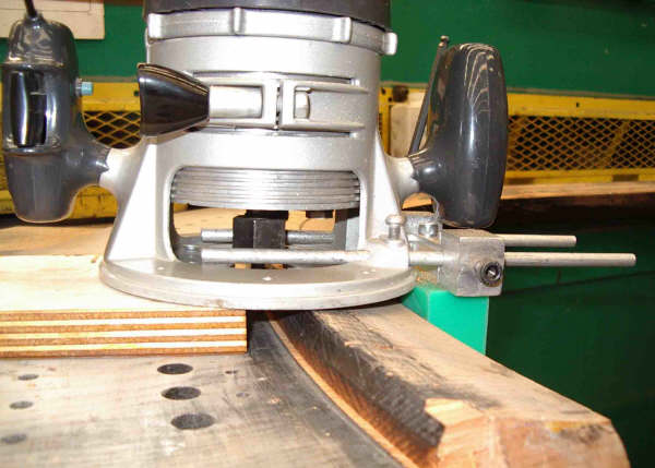 |
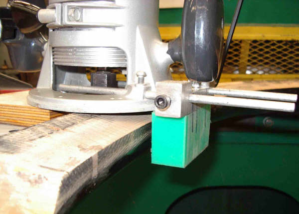
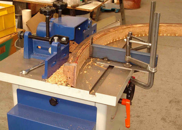
Router set to machine base board and rear of lower stop rail on the base board. Router is screwed to the plywood block, which is used with downward pressure to keep router square to the baseboard. Green nylon block is convex to follow the front of the stop rail. and needs tangential pressure applied towards the stop rail while the router is doing its job. |
 |
Second view |
 |
3rd view |
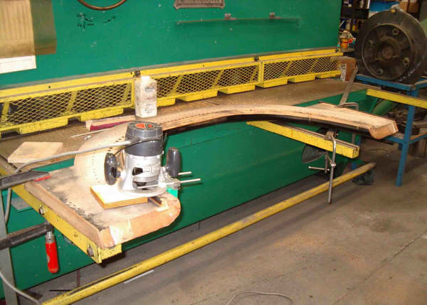 |
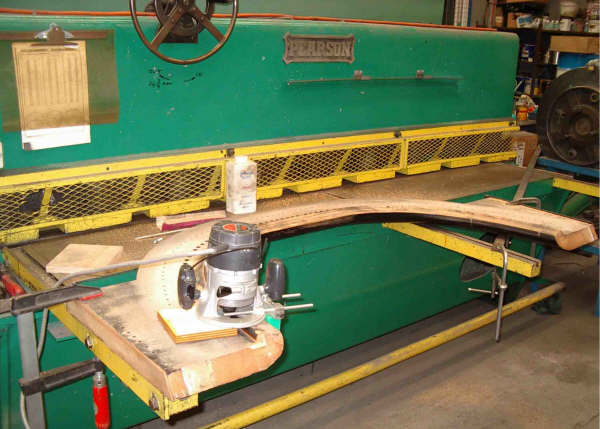
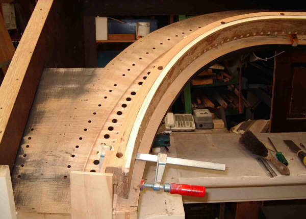
Ready to begin, with baseboard firmly clamped down. |
 |
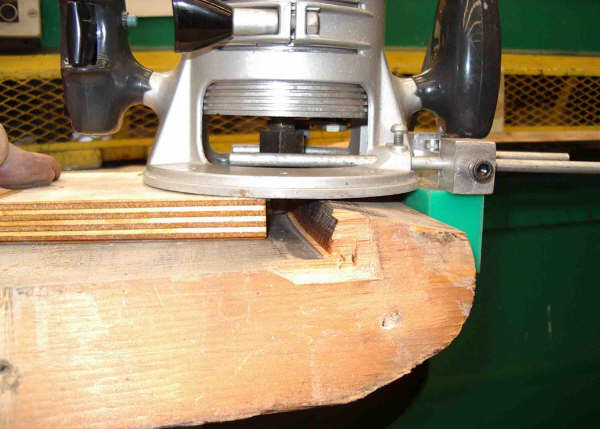
Talcum powder applied to baseboard to promote easy movement to the plywood block over the baseboard. Manual downward pressure is applied to this plywood block to maintain a vertical routing on the lower stop rail, and inward pressure applied to the green block to conform accurately to the front of the baseboard stop rail sweep. |
 |
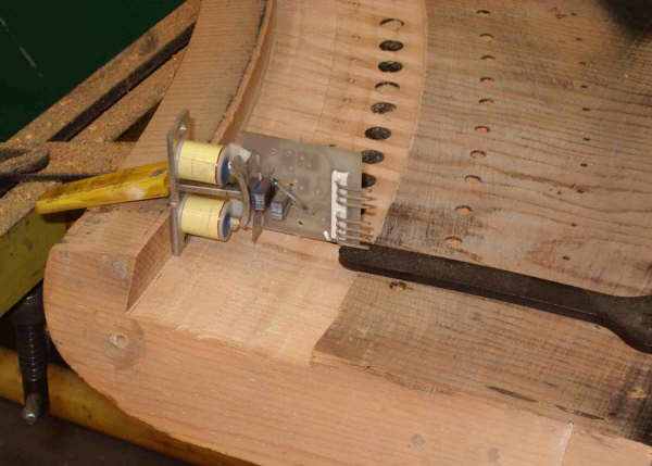
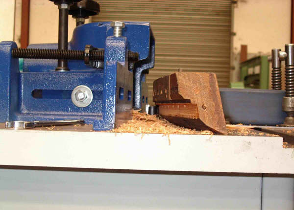
Routing completed, and allows access to the lower SAM mount for pre drilling for the screw.....which I use a Robertson pan head square socket screw, which is easier to screw in than a phillips, the bit of which easily slips out, wrecking the screw head.
I use a specially made long (18" long) drill and an equally long screw driver shaft. |
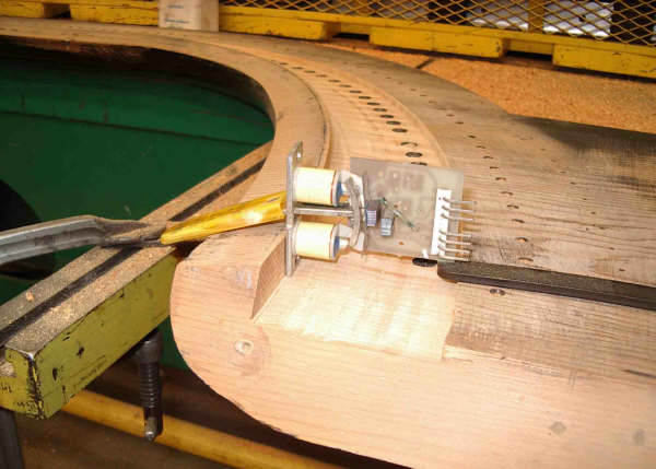 |
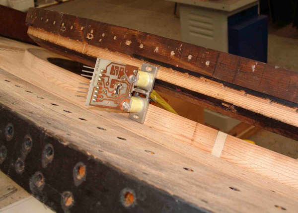
Relative position of SAM |
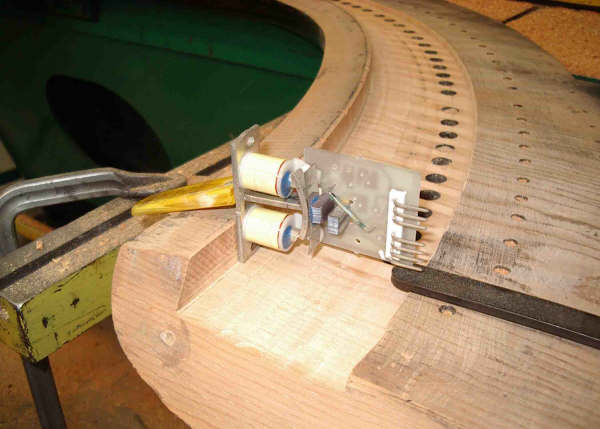 |
Second view |
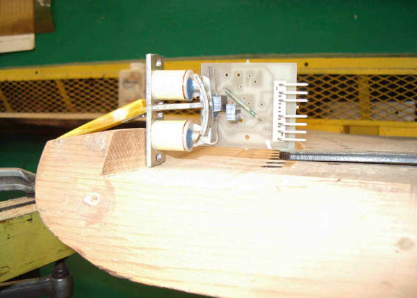 |
Close up |
 |
Close up |
 |
General view |
 |
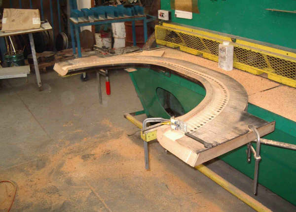
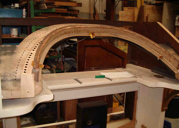
Baseboard mounted in console. |
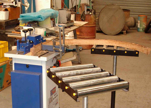 |
Spindle moulder set up for top stop rail. Two roller units keep the rail supported through the machine |
 |
Guide clamped to spindle moulder top to keep stop rail accurately located and vertical. |
 |
Spindle moulder at work!! |
 |
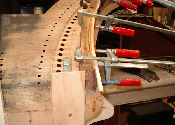
Top rail checked for position with 18mm thick hooked spacers...the hook shape stops the spacers falling out!! |
 |
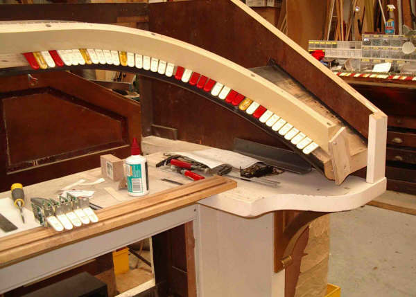
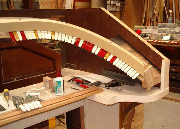
SAM in position |
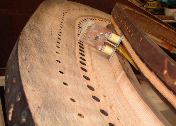 |
SAM in position |
 |
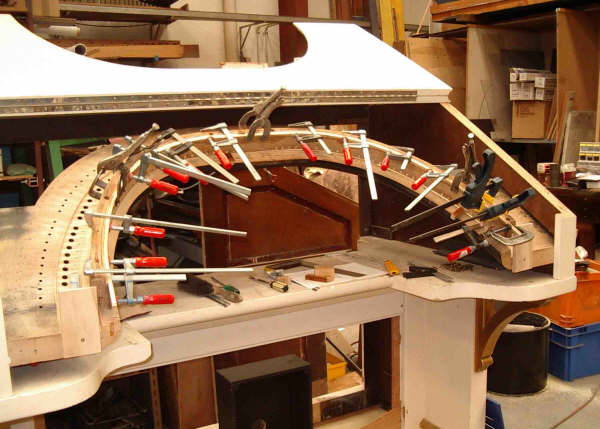
Checking fit of console top |
 |
Fitting 3/8" square filler into routed recess to re instate this area that was shaved off to allow clearance for the Reisner SAMs. |
 |
Same |
 |
Another view |
 |
Finished filler....spacers in place and front location timber screwed in to locate front of stop rail. |
 |
SAMs in position.......YES, it is a Christie 2man....to be a three man TO console in the background!! |
 |
Same |
 |
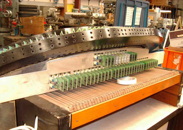
SAMs fitted....New Backboard with SAMs fitted |
 |
another view |
 |
Another |
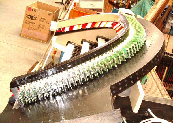 |
Yet another |
 |
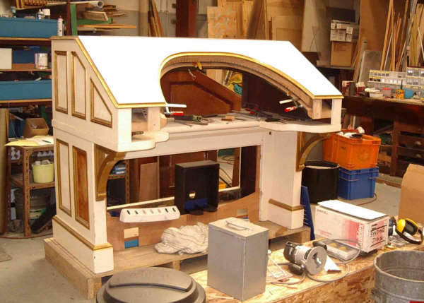
Console nearing completion |
 |
Console nearing completion |
| A few more general notes.................. Additional Note: One thing I did not mention, and I don't have a photo of it, is that I make up angle iron support brackets to fit under the baseboard, and sit on the key desk. With these supports , one each side, screwed into the base board, you can remove the end panels from the console to get at all the SAMs for drilling and screwing them into place. The steel frame stays located in the console, so you can remove the ends for servicing and wiring. You can still hinge the top section of the console to get at the manuals, and the back board is attached to the stop rail assembly as well! Julien
|
| SAVETHEORGAN.ORG wishes to thank Julien Arnold for sharing this information with our site visitors. |