PIPE ORGAN REGULATOR CONSTRUCTION
PROJECT
BY JOHN DEMAJO
BY JOHN DEMAJO
DISCLAIMER: The author of this site wants you to know that he is 100% in favor of the preservation and correct restoration of historic pipe organs and their related components. These projects are not intended as a guide for the repair of an existing theatre organ toy counter. They were developed for the use of persons who wish to add a toy counter to an organ that either was not originally equipped with one, or in the case of virtual organs, where an owner desires to have a mechanical "moving parts" devide that is visible or usable on an electronic organ. Under no circumstances do we advocate the use of these devices, or the application of this technology as a means of retrofitting an otherwise working or repairable theatre organ original component.
This is a wood-working project to produce a simple slide-valve regulator for pipe organ use. All components of the regulator are constructed with standard "home improvement store" lumber and material, with the exception of the leather components, which are made from standard Organ Supply Industries leather stock.
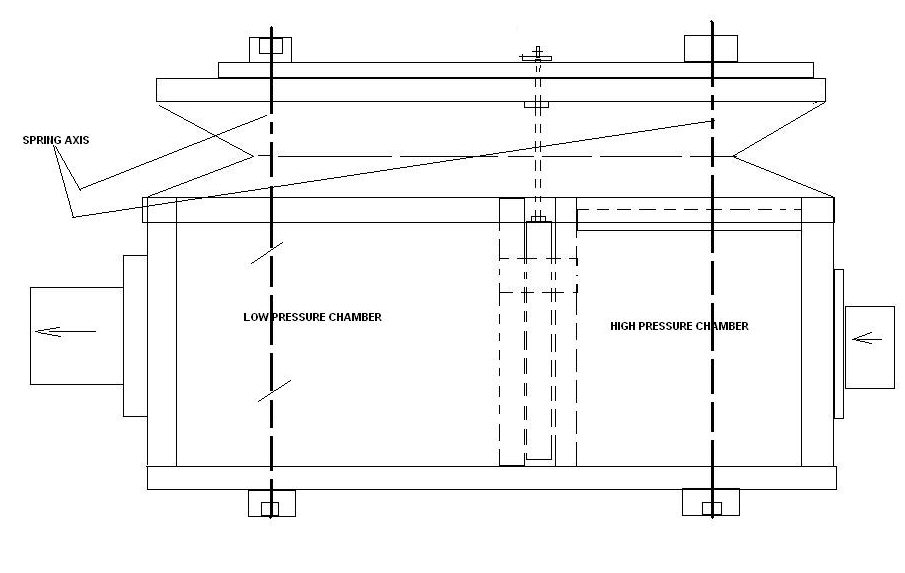
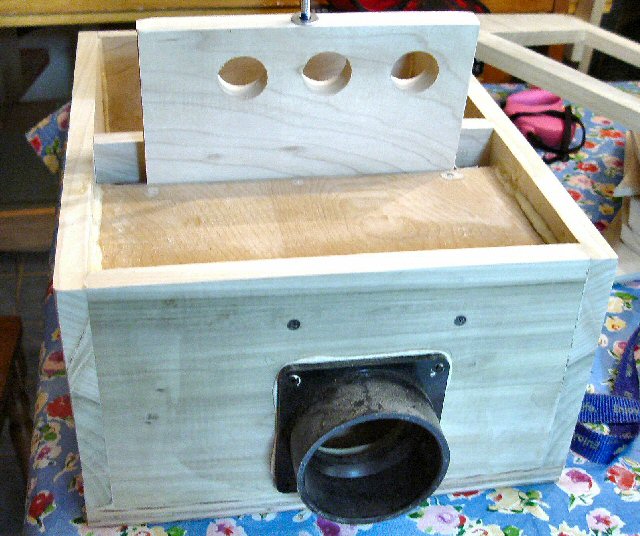
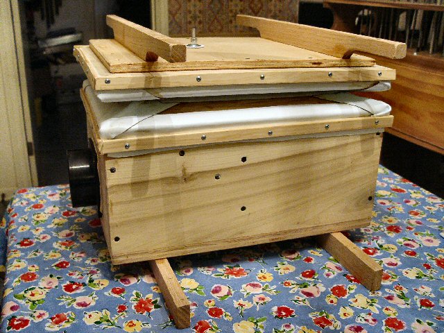
Side view of the simple 14" x 18" single-stage regulator. This will become the Vox Humana regulator for my pipe organ. Note the enclosed and sealed high pressure chamber at the right of the regulator body. The valve plate (shown extended) is sandwiched between the side of the high pressure chamber and a second baffle that admits the air to the low pressure chamber. As the top of the regulator rises, the holes in the valve plate also rise, closing off the passage of air from the high pressure chamber into the regulator body. Aluminum strips at the two sides of the sliding valve, keep it in alignment and act to further seal the passageway against leaks.
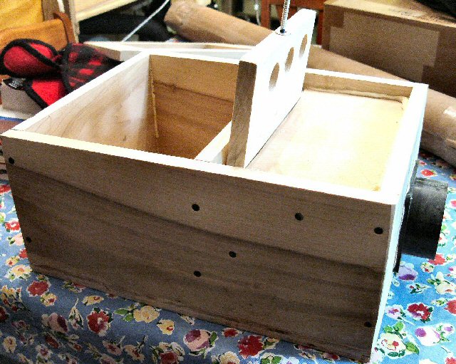
In this view, the air valve ports can be seen clearly. The unit is basically a curtain valve regulator using a wooden valve plate. A more appropriate name for this may be a "guillotine" valve.
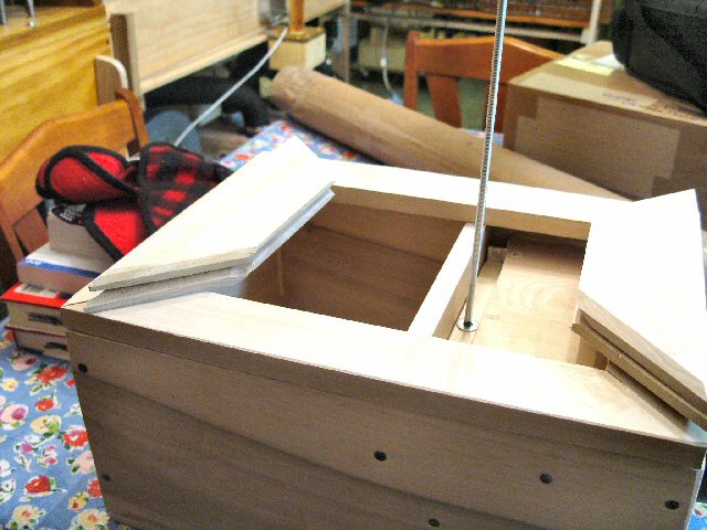
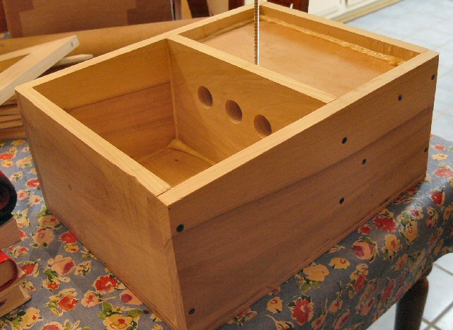
In this view, we show the regulator body with the pre-constructed top frame sitting in place to assure that everything is square at the corners and that the dimensions of both sections correspond. Next we will begin to install the ribs (shown at the left and right edges of the top frame) and begin the task of leathering them into place.
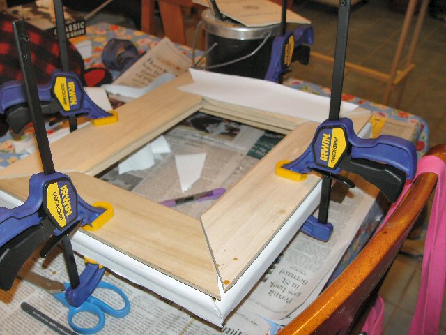
Upside down view of the regulator top frame. The upper ribs have been installed and leathered into place. Here we are about to install the leather that connects the inside of the upper and lower rib sections. At this stage, all four sets of ribs are clamped into place to assure that there is adequate clearance at the corners and edges when the regulator is in the fully deflated position.
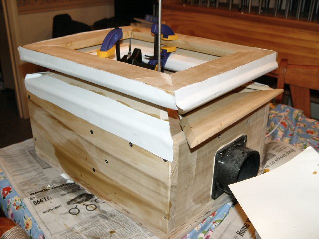
Regulator shown with rib leathering in progress. The top is set in semi-open position to allow leather application.
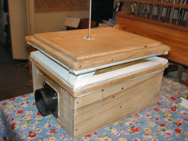
Leathering is completed
Completion of woodworking. All that is remaining is installation of four springs
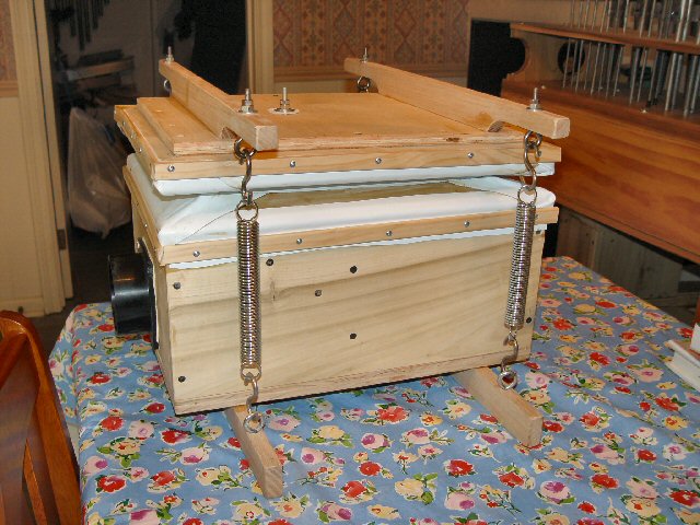
The final product!